Lab 11: Localization on the Real Robot
4 minutes read •
Simulation
I started by verifying that the lab11_sim.ipynb file successfully produces the same localization results as from lab 10. From the image below, you can see that we obtain the expected outcome. Again, you can see the unreliability of the odometry model…
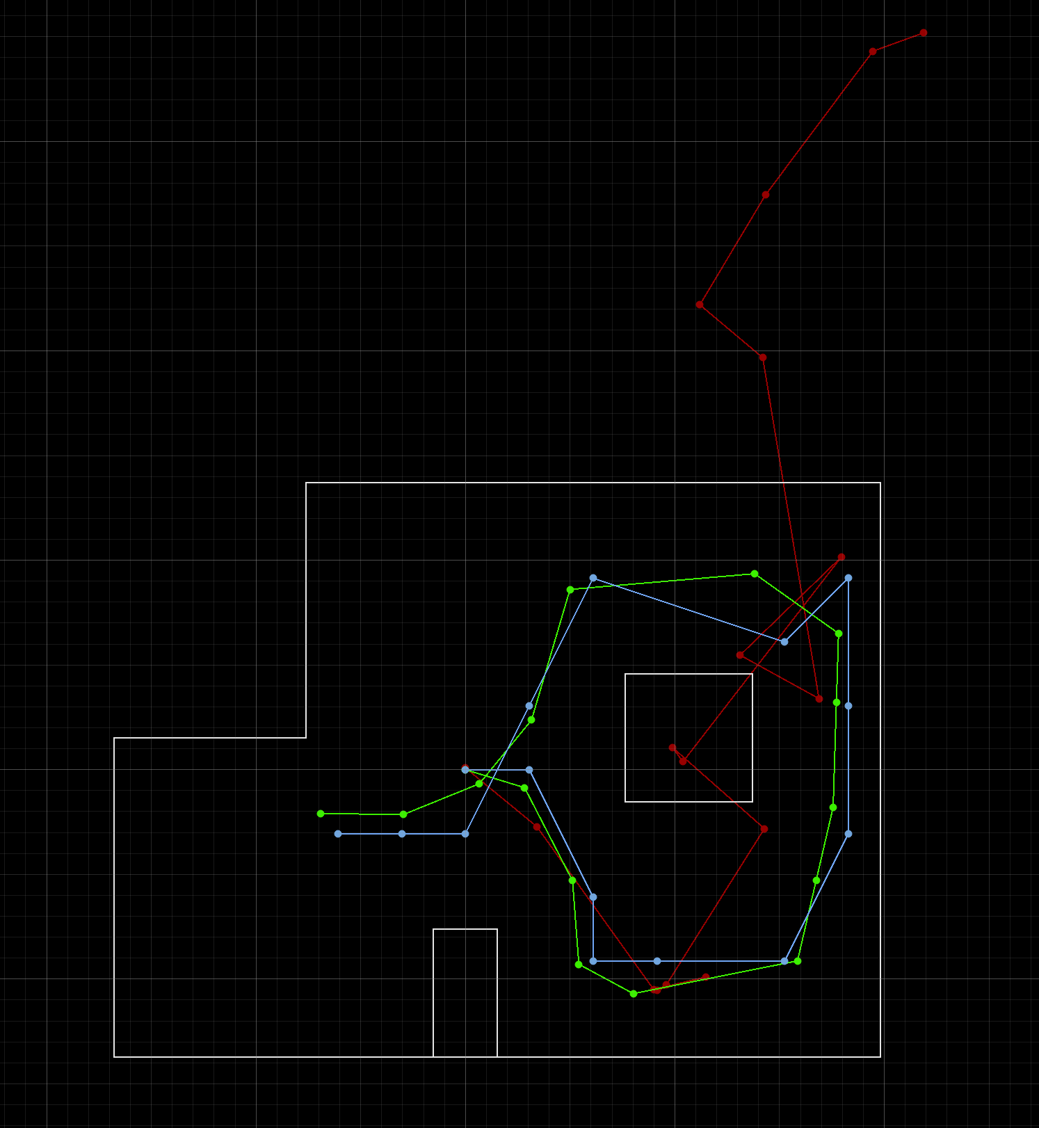
- Blue: belief pose
- Red: odometry model
- Green: ground truth
Robot Implementation
Python Code
Until next lab we do not have a way of determening ground truth for the robot; for this lab only the update step of the Bayes filter is implemented via the perform_observation_loop() function shown below. Its purpose is to perform the observation loop behavior on the real robot and return two column numpy arrays: (1) ToF range values (meters) and (2) sensor bearings in degrees.
In the function you can see that the SPIN case is called over BLE. It is responsible for conducting data collection and is further discussed in the Arudino Code section below. After the data is sent over BLE post collection, it is piped into a CSV file via the notification handler and passed into the localization algorithm by parsing through the CSV.
# Import libraries
# Clear file
# Run SPIN case over BLE
# P|I|D
# Ensure that the mapping file exists and is done populating
await
# Read data from the CSV
=
= . # shape (N, 1), in meters
= .
return ,
Arduino Code
A good deal of code and groundwork was reused from my lab 9 in order to have the robot spin on axis and collect DMP and ToF data. Angular PID was used via the DMP to reliably arrive at each target angle. The main difference is that for localization, I wanted to ensure that each measurment was as accurate as possible and that only a set number of ToF measurments were being taken. To achieve this, the ToF measruments were taken only when the robot arrived at each angle. After arriving at each angle, the robot waits for 500 ms to ensure a steady measurment, then the new target angle is set and the robot moves again.
At first, I tried to take a total of 18 measurments (20° between each). However, this did not provde to be enough measurments for a reliable estimate of pose, thus I doubled it to 36 measurments (with 10° between each). Note that I had to update the observations_count: 36 line in the world.yaml file.
case SPIN:
Refer to lab 9 for a detailed breakdown of each function and sub function being called.
Results
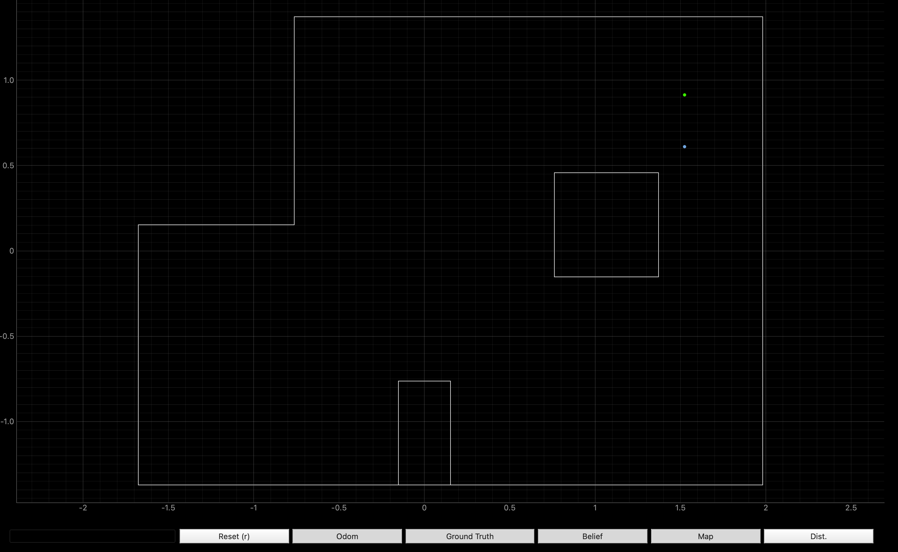
I localized about four different coordinates within the world. The true position of the robot is the green dot; the belief based on localization is the blue dot. From the four locations below, you can see that the localization is fairly good at getting close to the exact location of the robot, but is not completely accurate. From analyzing polar plots and ToF data, it appears that the ToF tends to underestimate which accounts for the deviation from the ground truth. For example, if you look at (-3,-2), you can see that the robot believes its closer to the corner than it really is due to this underestimation.
For lab 12 I to continue troubleshooting the ToFs. One idea is to fuse measurments from the two ToF sensors on the robot to reduce the effect of noise.


The following video shows the update step being completed at (5,-3)
Discussion
A good deal of debugging and trouble shooting was required to make the localization work. The change of 18 ToF to 36 ToF measurments was already discussed above. I also had to angle my ToF sensor up more to reduce ground interference. Furthermore, I played around with the sensor noise found in world.yaml and ended up reducing it from sensor_sigma: 0.1 to sensor_sigma: 0.05.
Collaboration
I collaborated extensively on this project with Jack Long and Trevor Dales. ChatGPT was used to help answer Bayes Filter implementation questions.